|
|
N4HCI BITX Projects |
The BITX-40
Christmas 2017 included some gifts from my wife to feed my Amateur Radio
spirits. Principal among them was a BITX-40 kit. This is a
VERY inexpensive kit designed by VU2ESE and sold for $59. Actual
cost will rise based upon the availability of an enclosure, microphone,
12 vdc power supply, and speaker in your shack/junk box. This kit
was a lot of fun.
For this first such kit since my Heathkit days, I chose buy a small
enclosure, a small speaker, and some knobs. Other items were in
the junk box.
Unlike WA4THR (see his BITX-40 experience
here), I did not hack this
design, preferring to build it and use it as designed, at least
initially. Ultimately, I did install a software mod that greatly
improved the user interface and information presentation. The only
hardware changes in my first build were the addition of a switch to
shift the radio to the software update mode, the addition of a terminal
panel in the radio for distribution of 12 vdc to various points, and
rewiring of an old IC2-AT microphone to make it compatible with the
BITX-40.
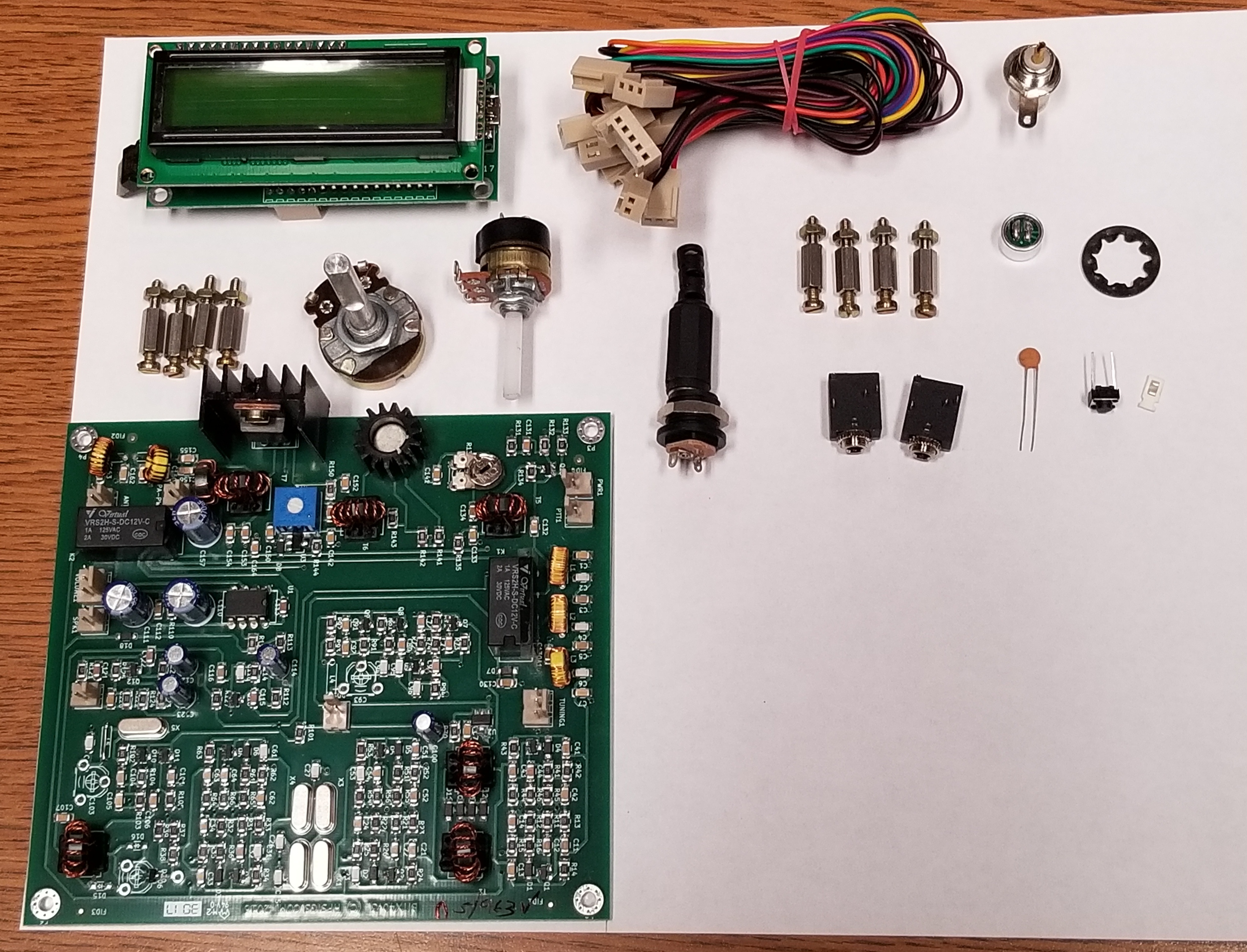
The parts, as received from HFSignals, are shown below:
A simple kit box was acquired and it was assembled. This photo is
a work in progress showing a tight fit.

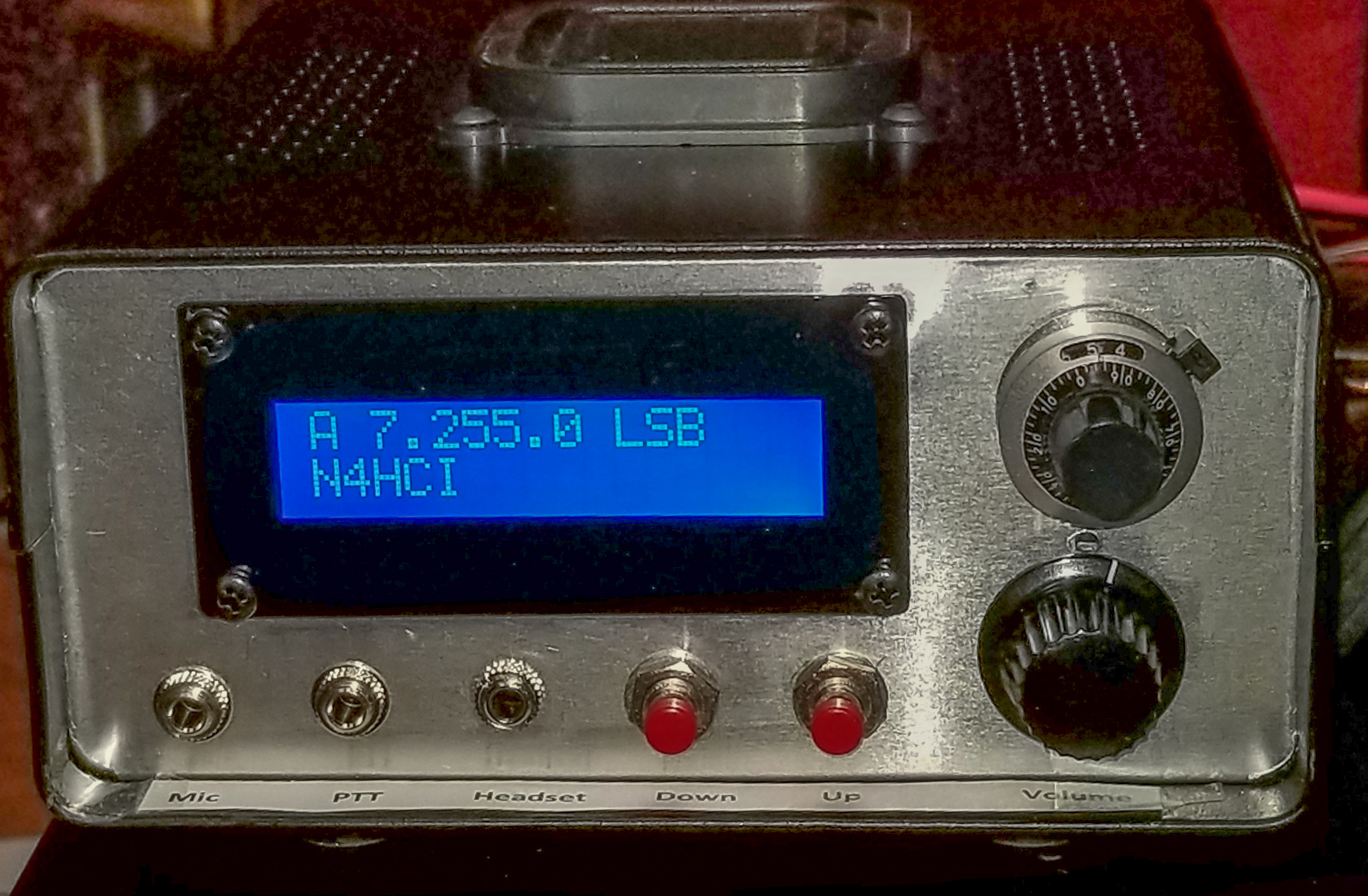
And the display after software upgrade
This was NOT the end of it. The BITX-40 is a 40 meter radio.
In Dec 2017, HFSignals released a brand new transceiver called the
uBITX, which is a general coverage receiver and covers all ham bands,
for only $109. So, I convinced my wife that her Christmas gift
also included the uBITX but that it remained to be ordered. She
agreed and the order was placed, including a $10 premium to have the
shipping handled by DHL, instead of the Indian Postal Service - which is
a 3 week delivery prediction. Alas, what I overlooked when I
ordered was that the uBITX had suddenly become very popular and had a
huge waiting list. Delivery eventually became 2 months even
bypassing the Indian Postal Service as they cleared the backlog of
orders in front of mine.
So, with time on my hand, I decided to build the enclosure for the
uBITX.
UBITX Enclosure Sub-Project
I found a reference to making enclosures out of printed circuit boards,
and I happened to have a good supply of unused double sided PCB material
from a previous project. Based upon my experience with the
slightly small enclosure for the BITX-40, and WA4THR's BITX-40
experience with making physical modifications to the radio that consumed
space over that of the basic HFSignal kit, I decided to make this
enclosure larger than seemed necessary by the size of the uBITX circuit
boards. I settled on 8" wide by 7" deep by 3" tall.
A design was sketched out for a bottom, top, front, rear and 2 side
pieces. Parts were cut out of the stock PCB with a saber saw after
scribing cut lines on the PCB material, edges were sanded, and then the
pieces were soldered together using a 150 watt soldering gun inherited
from my father. The instructions that I'd read on soldering PCB
material together cautioned me that solder shrinks and caused circuit
boards that are soldered at a 90 degree angle to actually be 88 - 89
degrees when cooled. He provided a way to avoid this problem by
increasing the angle to 91-92 degrees before soldering -
but I thought that I had a better way,
and chose to use picture frame clamps to force the cooldown to occur
while the PCB material was fixed at 90 degrees and could not move.
Alas, for some reason, that did not work [Teaching Moment: The stupid
shall be punished] The consequence of ignoring this sound advice
was not too bad and I was able to proceed, although the end result would
have been better if I had heeded the lesson learned.
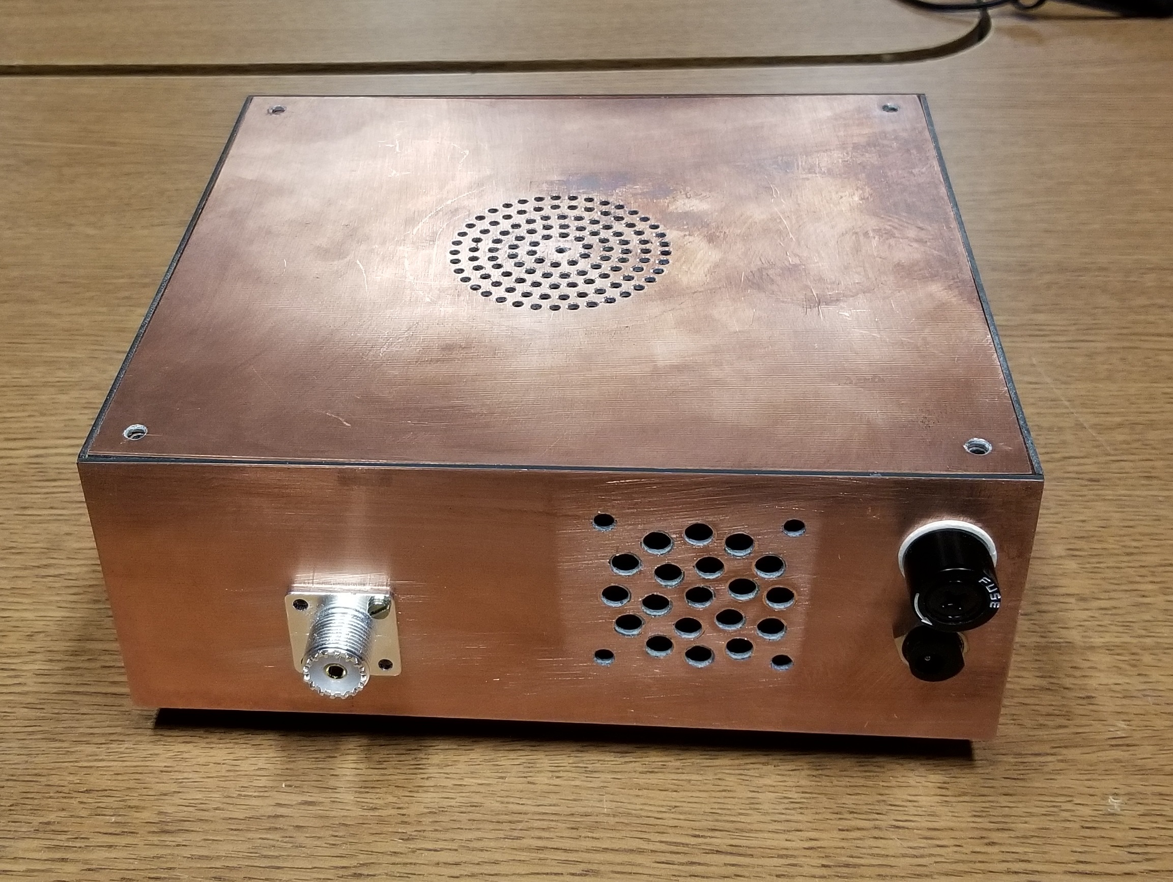
The following pictures provide the results of the enclosure project.
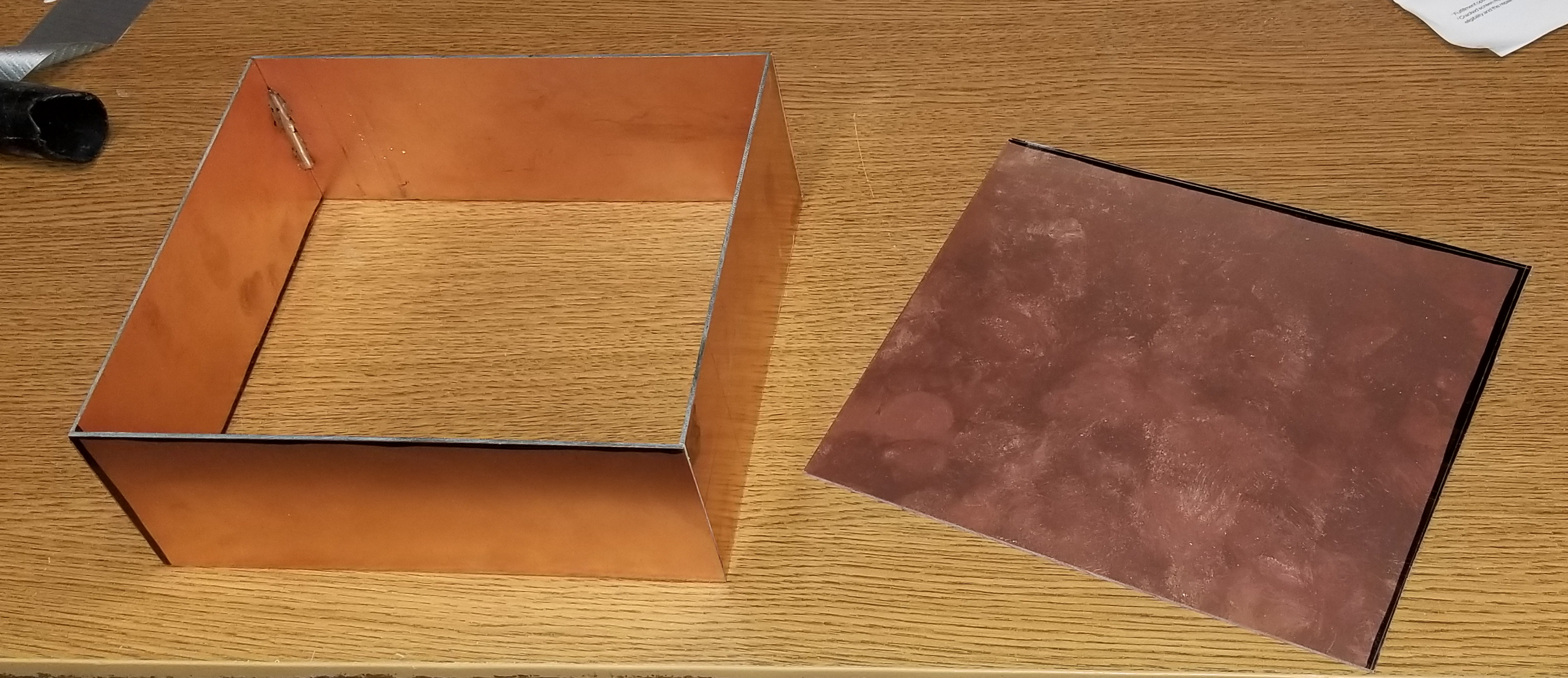
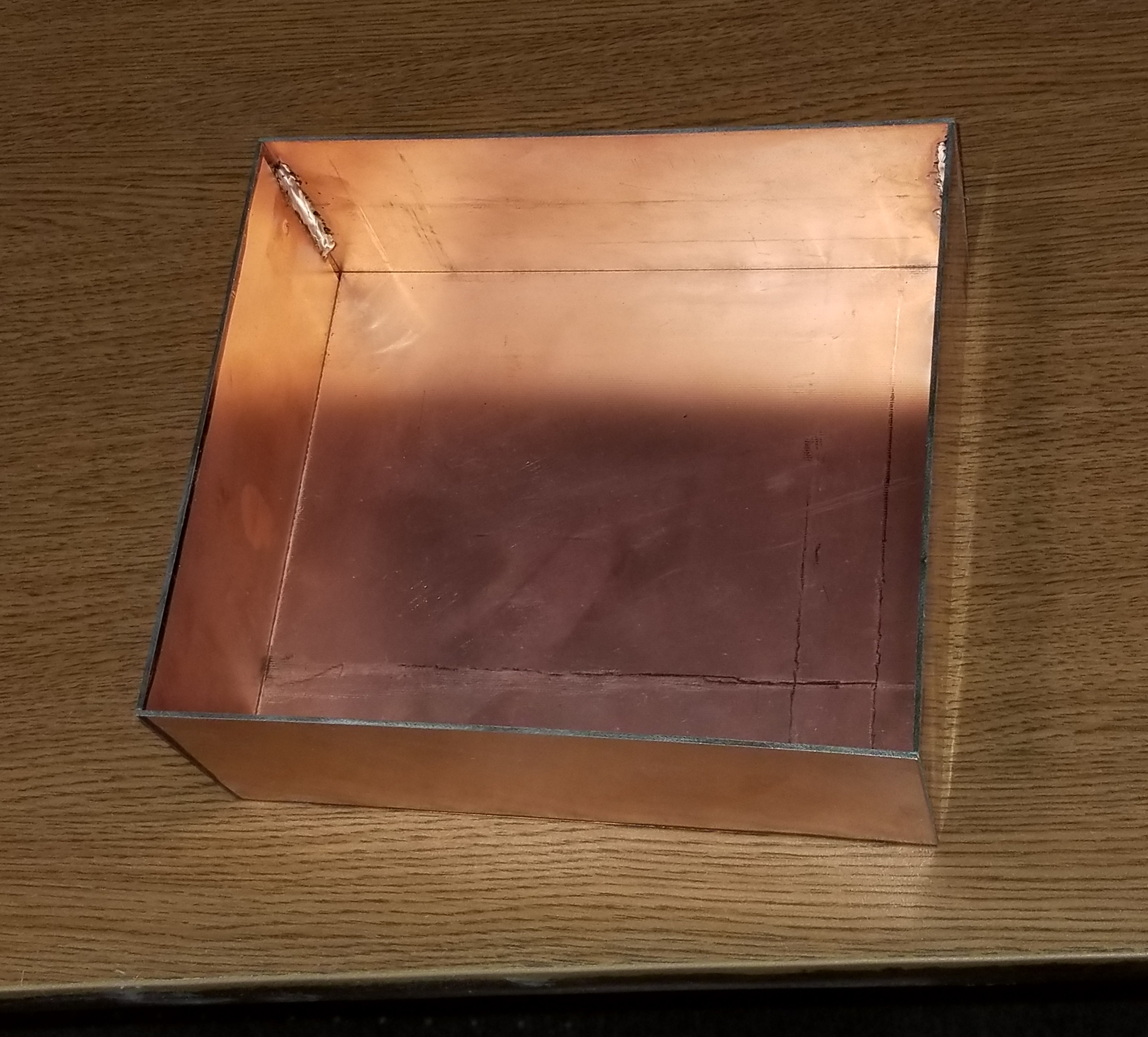
Front, rear and side panels soldered together
Bottom inserted and ready for soldering
uBITX Project
The uBITX, like the BITX 40, requires the builder to provide knobs,
speaker, and in this case, I decided to install a fan to cool the power
amplifier heat sinks. With the enclosure built, and the
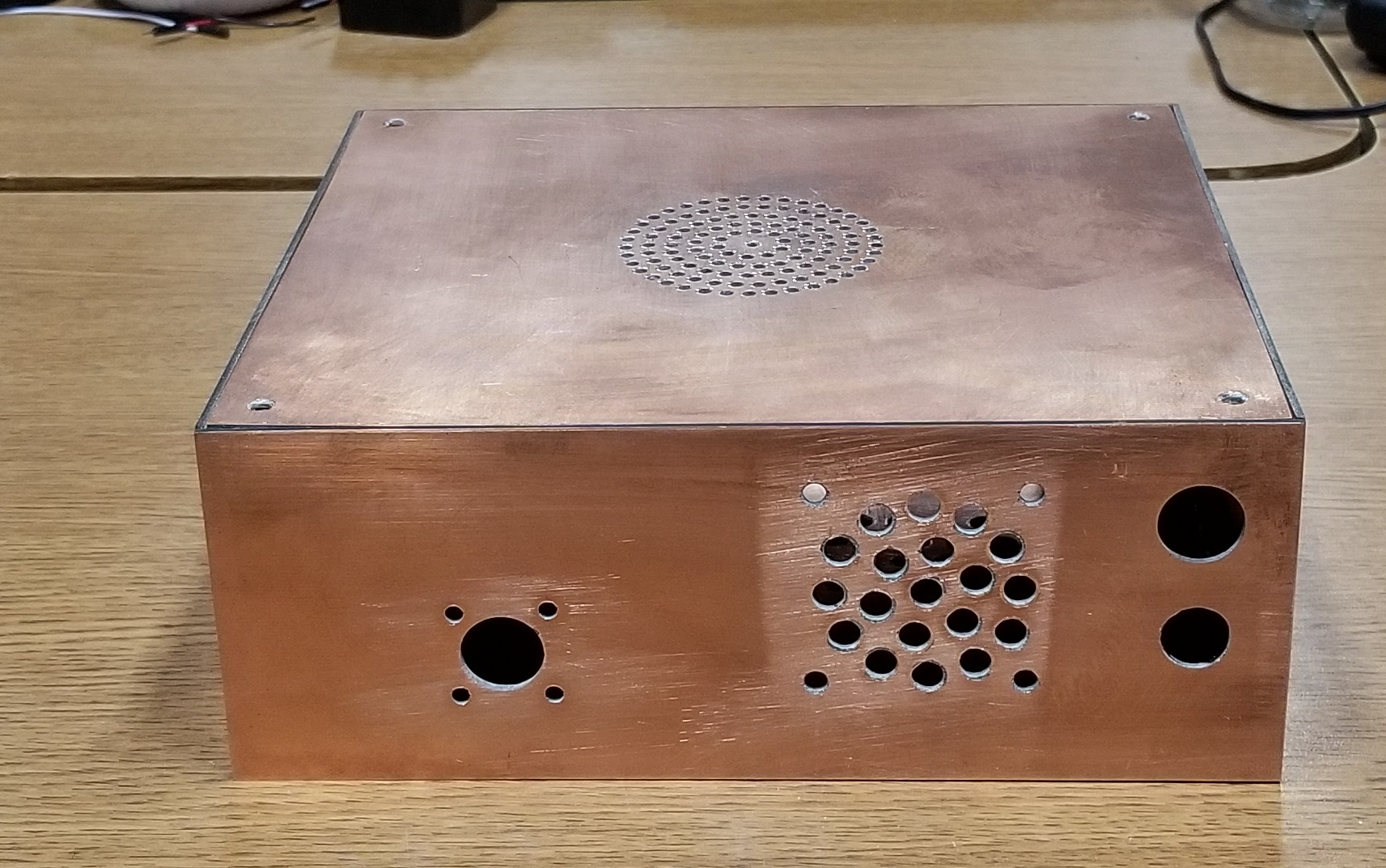
eventual arrival of the uBITX components, the enclosure was cut and
drilled for the actual fitment of the uBITX parts, the selected speaker,
fan, SO-239, and fuse cartrides. The front panel fitment was to
mount the parts for the LCD, tuning encoder shaft, volume control shaft,
and mini-phone sockets for microphone, external speaker/headphones, and
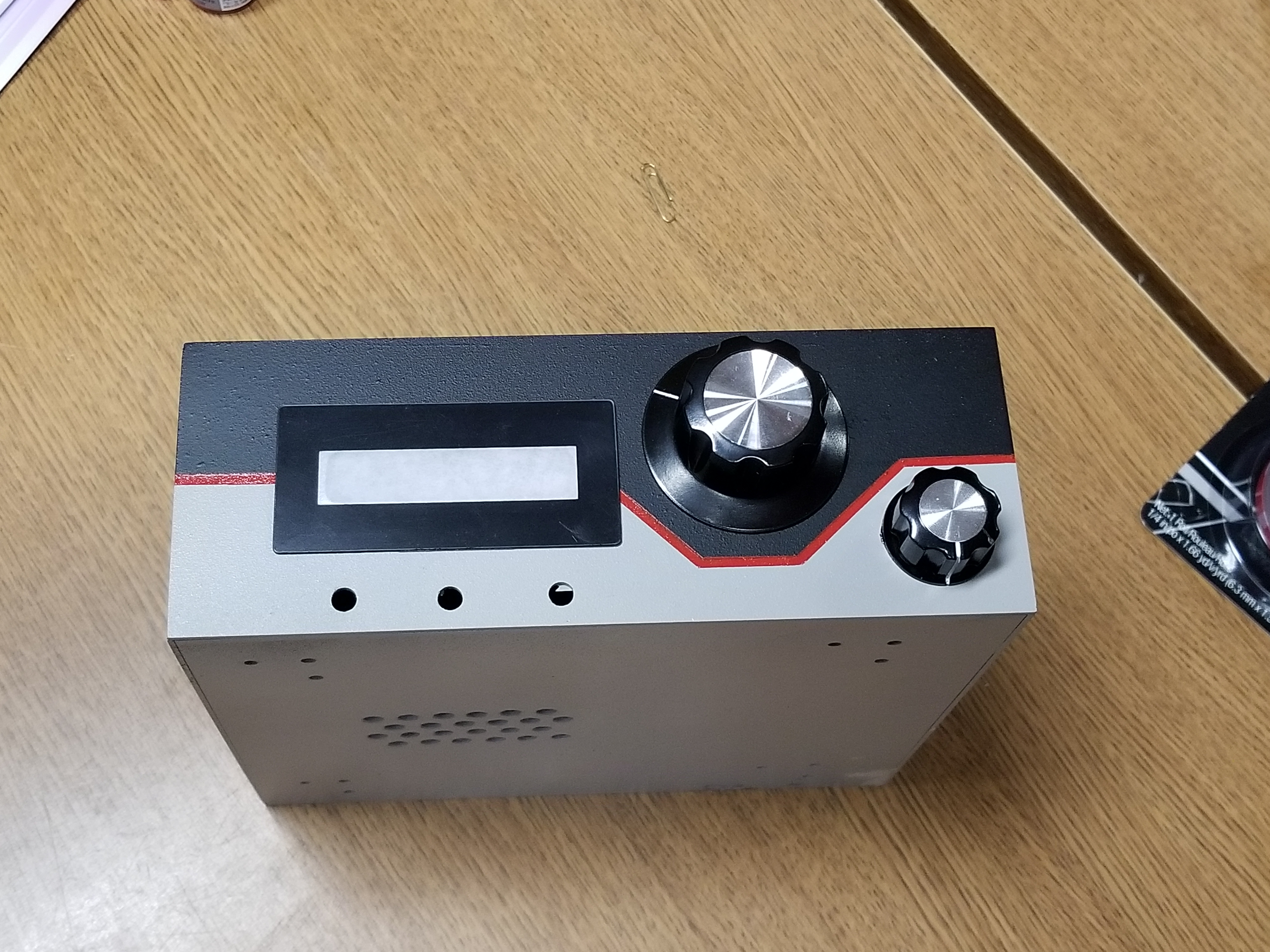
a CW key. The results of these cuts to the enclosure were:
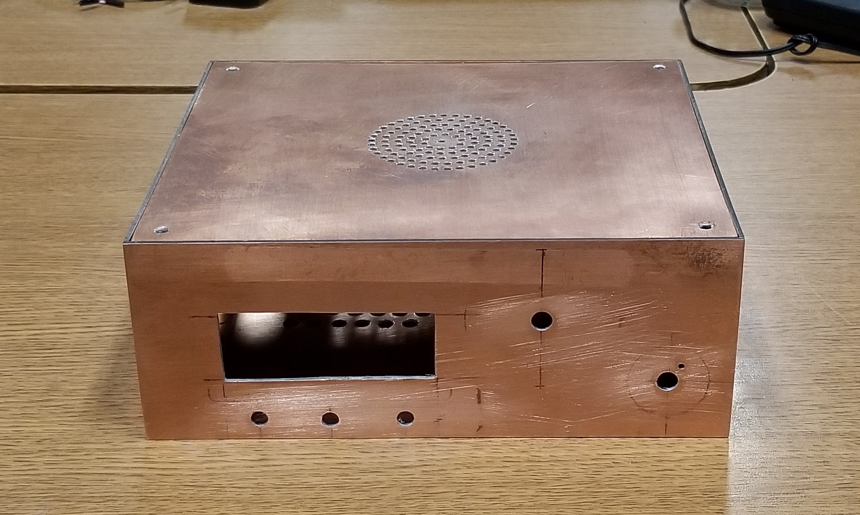
Front Panel and Top
Rear Panel and Top
The rest of the parts were assembled inside to check out fit up.
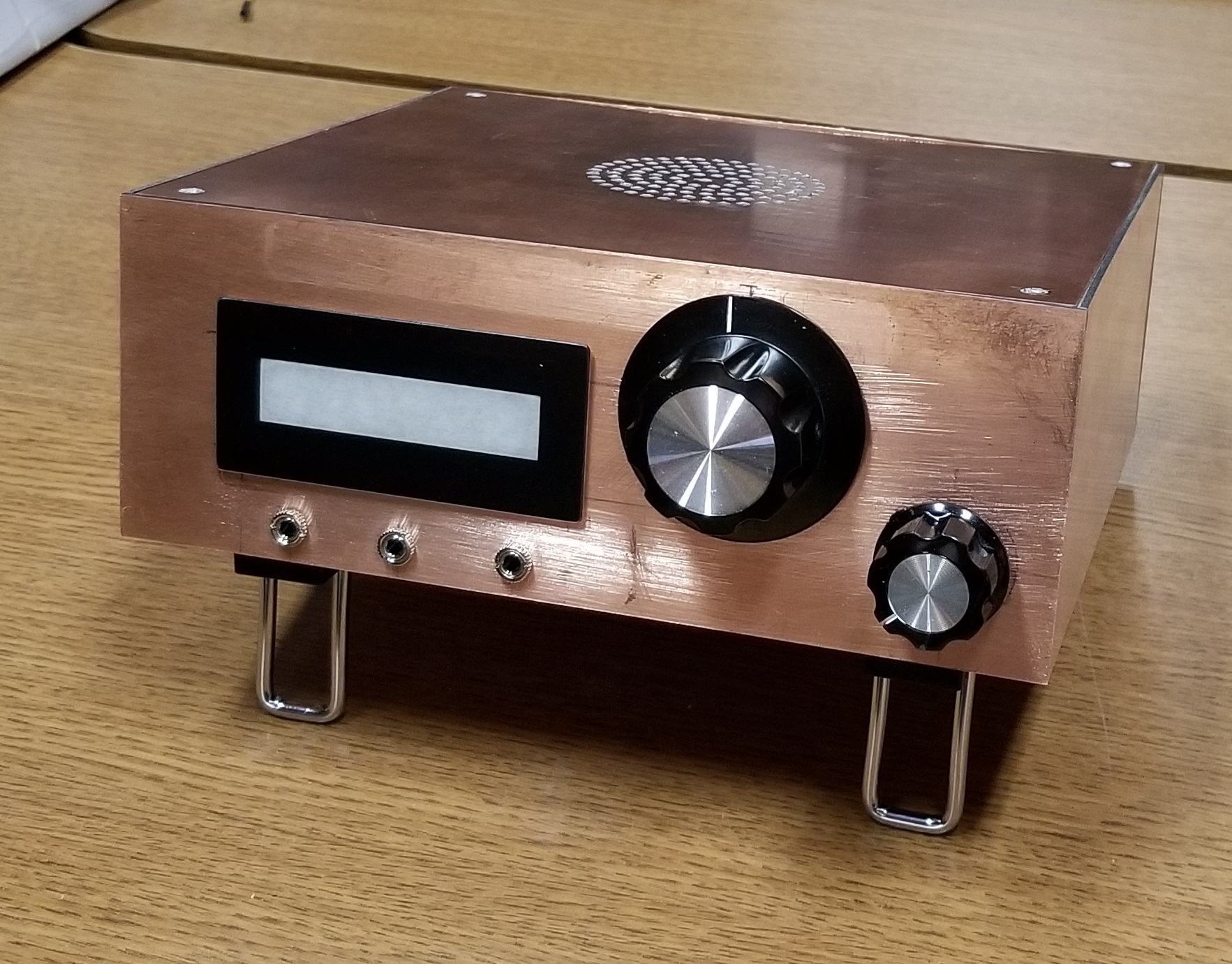
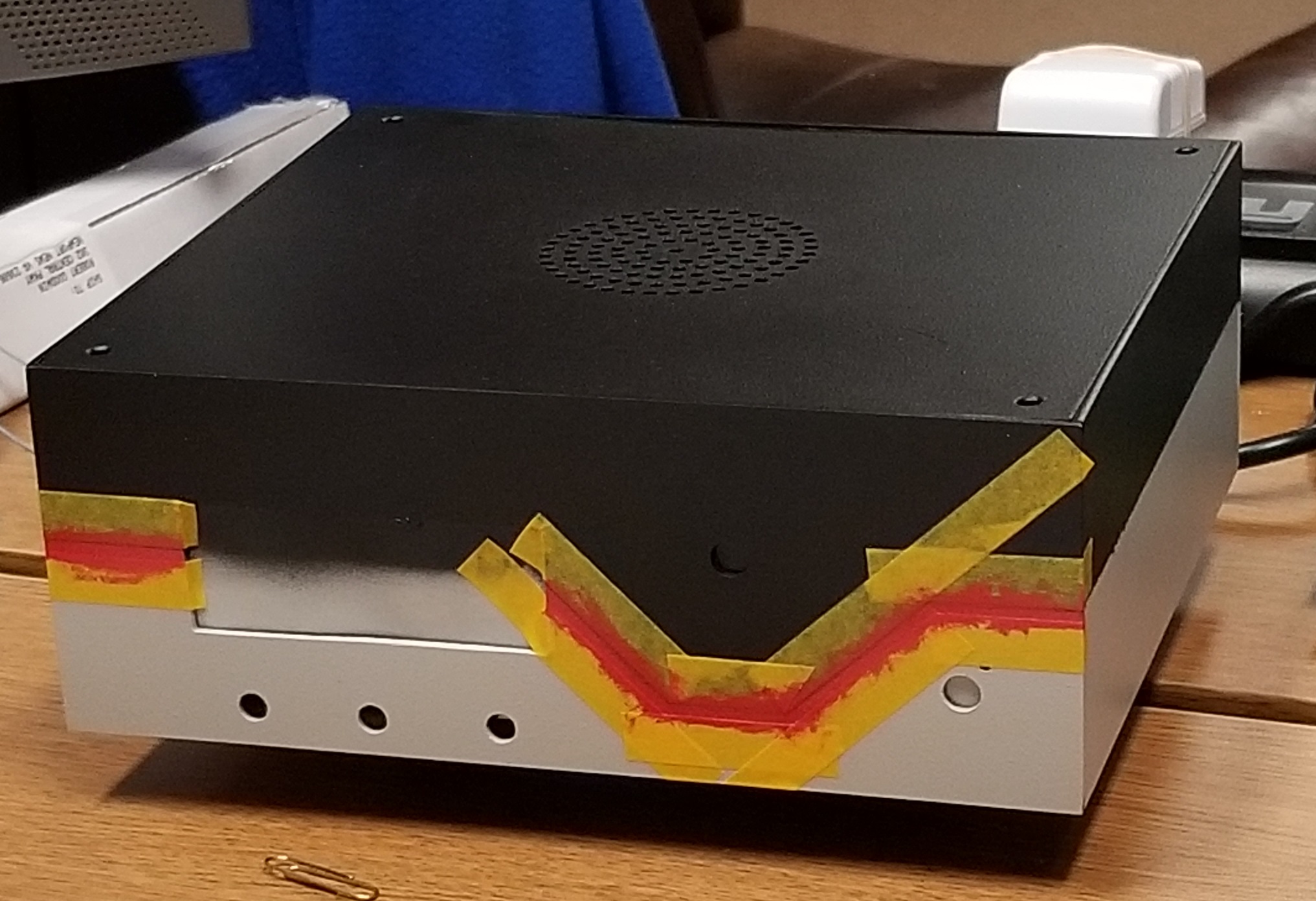
Then the parts were removed and the enclosure painted
After the parts were reinstalled in the enclosure, the rig was lit off,
calibrated, and tested.
But there are always changes to be made. The Power/Volume control
in the kit used an abnormal small size shaft for which my knobs were NOT
suitable. So I decided to make an adapter to fit on the small knob
shaft, using a 3D printer, which would enlarge the shaft to the 1/4"
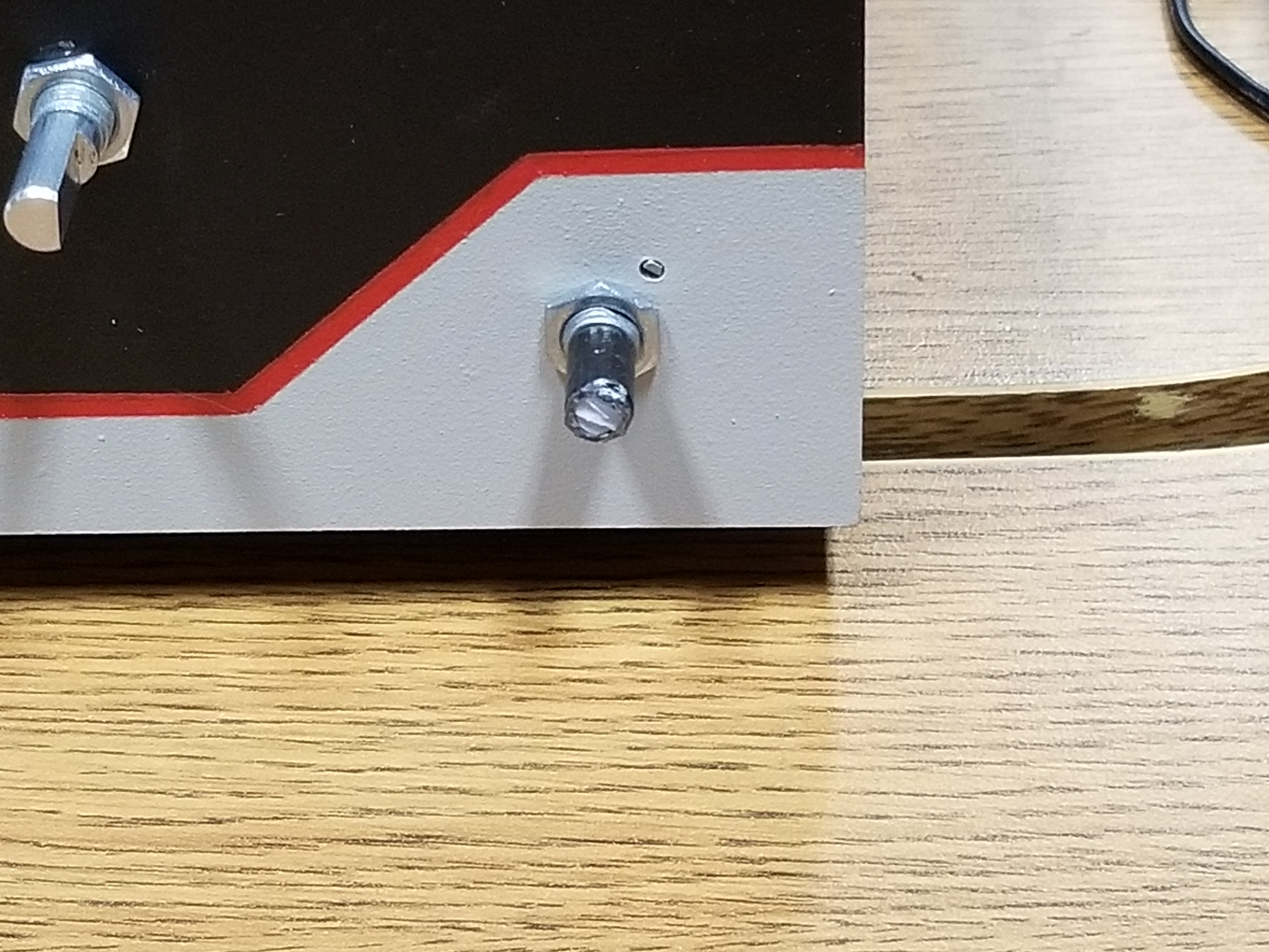
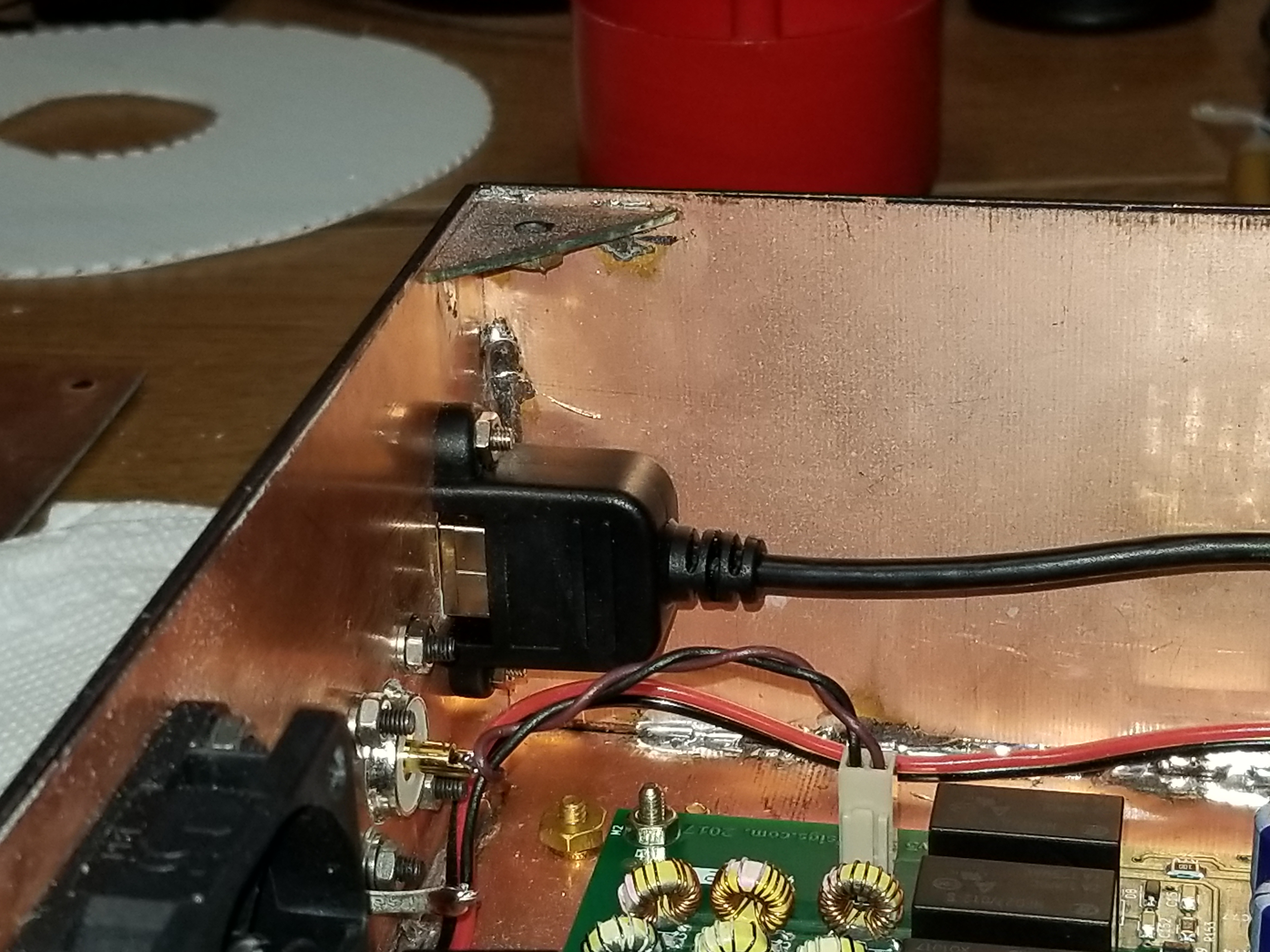
size the knob was expecting. Then, it was all ripped apart and a
cutout made for and a USB extension cable installed to bring the
internal USB connection out to the rear panel so that software changes
could be make without opening the radio and with an eye to eventual CAT
control of the rig.
After reassembly, labeling was applied and the radio finished
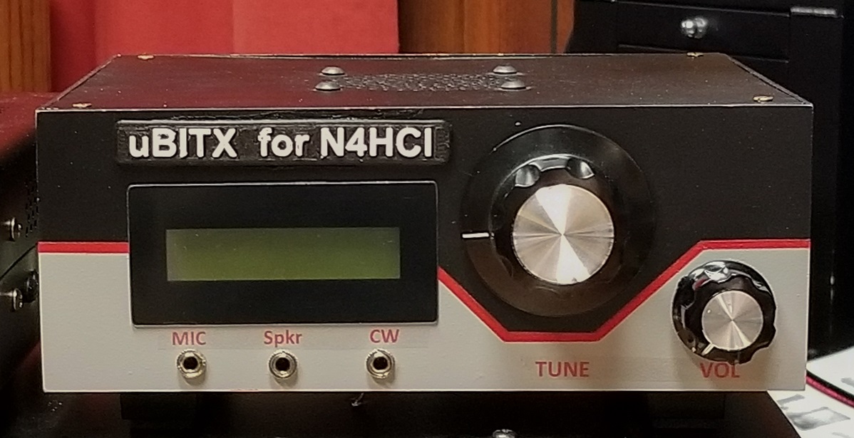
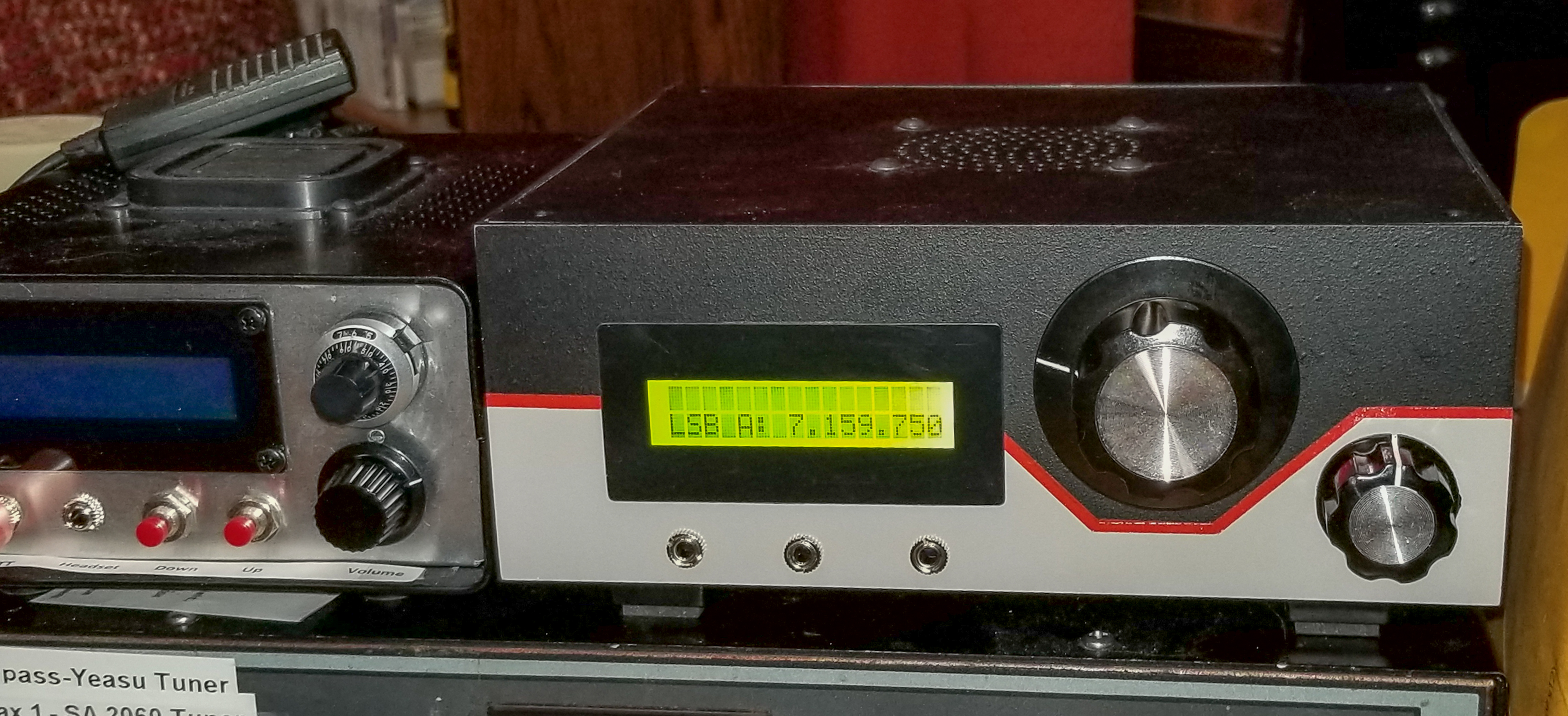
Finally, I found an improved software package and installed it for
improved user interface and control.
The End?
.